MY 3-IN-1 LITTLE SQUIRT - REPAIRS AND MODIFICATIONS 2002
17-July-02
As of now here is the status of Little
Squirt. I have finished the sailing gear
and have tried it several times. The PVC
mast was not suitable so I have purchased
a aluminium pipe to replace it. The pipe
is heavier then recommended, but it is all
I could get. I still have to reinstall the
sailing gear so I can use it.
I purchased a 36LB Min-Kota trolling motor,
which did not fit in the built in motor
mount. I built a separate mount on the
transom of the boat. I am in the process
of installing the box for the battery is
located just aft of the rowing box. I
considered installing it in the storage
compartment in the front but decided against
it due to the difficulty accessing this
area. I am also installing a 5-watt solar
panel on the bow of the boat.
26-Aug-02 Except for some adjustments to
the safety for my electric engine which I
will post when done I consider little squirt
to be complete I will show pictures and
explain the modifications I have made to
the plans.
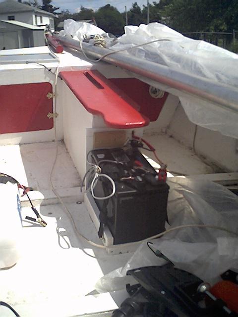
Ignore the clamps on the far left of the
picture. They are from my nautilaus
battery charger and are not part of the
boat.
Solar Panel:
I installed a 5-watt solar panel to the bow
of the boat. I put it off center for two
reasons. It left one side of the front deck
clear so I could safely walk on it with
risking stepping on the solar panel. It
also left room so if for some crazy reason
I wanted to install another panel. I bought
the panel at Canadian Tire. I ran the
cable aft and through the forward bulkhead
into the storage compartment. I then ran
it through the daggerboard box. I was
careful to secure the cable on the side of
the box away from the daggerboard opening,
and up near the seat at the top. I did not
want the daggerboard to pull on the wires
when inserting or removing the daggerboard.
I then cut a hole in the front of the
daggerboard box for the cables to go through
to go to the battery compartment. The
grey wire in the picture is from the solar
cell. There is a white rope running across
the deck from the bow of the boat. Dont
let it confuse you. I guess I should have
cleaned up before taking the picture. I
have been asked if the solar cell is of any
use. I can not definitely answer the
question. When on the water and running
off the engine it gives me a lot of piece
of mind knowing it is there. It may be
slow a molasses but I know it will
eventually charge the battery enough to get
home. I also believe it will extend the
range of the battery if it is hooked up
while the engine is running. I tried to
find out how well it would charge the
battery on its own twice after a good run
when the battery was discharged. The first
time I found out that my battery was
defective, and would not charge, and the
second time I found out I had a loose
connection in the connector for the charger
that stopped the charge sometime during
the process. Since I did not know when it
stopped charging the battery it made the
information I collected during my second
experiment worthless. All the voltages I
recorded are on this site under adventrues
in a 3-in-1 or under the battery power
consumption table below.
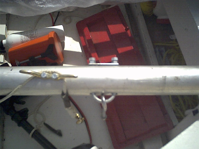
Battery Box:
The battery box was made by sizing a piece
of plywood slightly wider then the battery
and slightly higher. I then attached the
plywood to the daggerboard box. That part
of the box is made of ¾ inch wood so you
can drill a few screw through to hold it
in place. I then put the battery in place
and cut 2 pieces of wood for the side
supports and a smaller one for the front.
The theory behind making the board smaller
in front is too make it easier to get the
battery in and out. I attached this boards
by countersinking screw through the bottom
of the hull and into them. I then filled
the holes with silicone and repainted.
The battery is held in place with a battery
hold down strap near the front of the
battery. I also took a small piece of wood
and put in on top of the battery at the
daggerboard box. I then put two screws in
too hold the board in place. I theory this
should hold the battery in place in the
back. I cut a piece of tarp to cover the
whole thing and cut a hole in each side of
the plywood attached to the daggerboard box.
These hold the bungie cord I use to hold
the Tarp cover. If you look closely you
can see the hole on the left side of the
plywood. The hole is partly covered by the
loops of the solar cell panel cable in the
picture.
Note: From the very few recharge rate
figures I could get in the 2002 season
I believe that the solar cell can recharge
the battery in between six to twenty hours
depending on the weather. (**THE COMMENT I MADE ABOUT THE SOLAR CELL IS WRONG.
WHEN A BATTERY IS DISCHARGED QUICKLY THE VOLTAGE WILL CLIMB FOR A COUPLE OF HOURS AFTERWARDS. ALL THE INFORMATION I HAVE COLLECTED ABOUT SOLAR CELL RECHARGING DO NOT TAKE THIS INTO ACCOUNT.**)
I also figure
I can run the engine for 2 hours at lvl 5
and 4 hours at level 3. Any lower level
then three is totally unacceptable except
when manuvering such as docking.
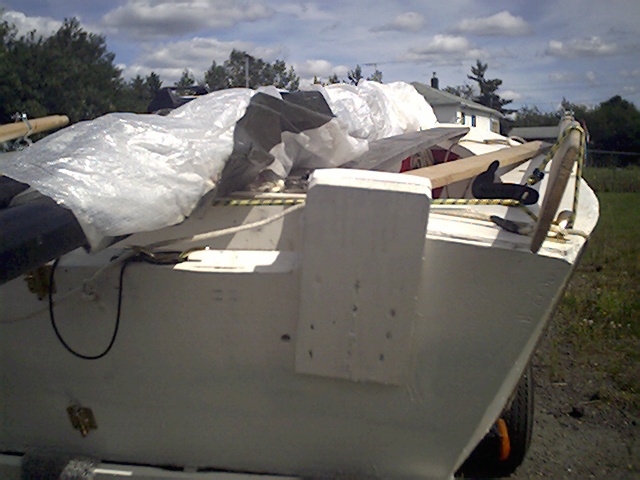
My Motor Mount (looking AFT)
My Motor Mount (looking forward)
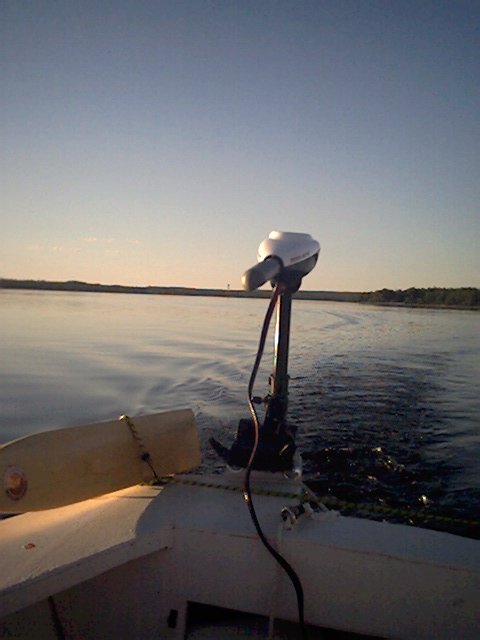
My Motor Mount ( In Action)
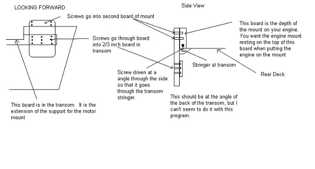
My motor Mount (Construction Diagram)
In order to build my motor mount I cut a
board measuring just slightly wider then
the distance between the two clamps on the
trolling motor. I wanted to give them just
enough room to clamp on. I then put the
board in the clamp and drew a line at the
bottum of the clamps. This is to ensure
that when you mount the motor the top of
the clamp unit is resting on the engine
mount and the clamps at the bottom are as
close to the transom as possible. This
line will be level with the top of the
transom when the mount is installed. You
now have to do some measuring. You want to
cut this board so that the line you drew
is level with the top of the transom and
the board extends far enough down so that
the screws you drill through it and be put
in the board inside the transom that is
the support for the engine mount. If you
did not install the optional engine mount
when you built the boat you will have to
glue a ¾ inch board inside the transom
large enough to support the mount. Round
off the corners and you are ready to install
this board. Put the board so that the
line you drew is at the top of the transom.
Put the screws through the mount and into
the transom being sure to put the screws
in so they dig into the board inside the
transom. When I did mine the board split
a little in the middle due to the slight
curve in the transom and the fact I probably
put in too many screws. It has not caused
me any problems. Once you have done this
take a second board and put it against the
board you have just installed so that it
is resting on the top of the transom and
forward of the first board. Draw a line so
that the second board is the same shape as
the top of the first board. Cut your line.
I glued the second board to the first and
put a few screw in to hold them together.
I also drilled two screws into the sides of
the second board angling them downwards so
they would dig into the stringer that was
used to join the transom and upper deck.
If this confuses you I have been told I
give awful instructions, but all the
information is here.
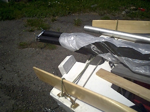
Mounting the sail with a U-Bolt
In order to mount the sail to the mast the
plans call for you to get two o-ring bolts.
You are then supposed to open the O on one
and insert the other into it. You then
close the loop and the two bolts are joined
together. The only type of bolts I could
get are solid steel. Has anyone ever tried
to bend steel hardware. I came up with
this alternate solution. I took a u-bolt
and drilled two holes in the mast equal
distances from the point where the original
bolt would have gone into the mast. I then
looped a o-ring bolt over the u-bolt and
installed the u-bolt through these holes.
So far I have not had any problems with
this modification.
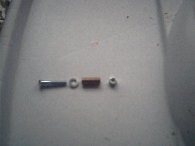
MY SAFETY DEVICE DISASSEMBLED
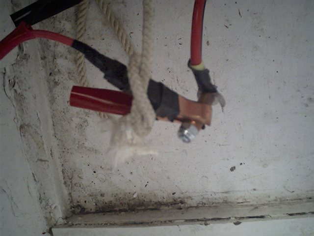
MY SAFETY DEVICE INSTALLED
This is the newest version of my safety
device for the trolling motor. My trolling
motor has no version of a dead mans switch.
If you let go of a typical motor it will
shut off automatically. This insures both
that the boat does not leave without you if
you falls overboard, and it reduces the
chances of the prop cutting into you.
Originally I took a clamp at the end of the
battery cable and connected it directly to
the connector to the engine. However
because of the small surface area of the
connection the engine constantly cut out
unless the clamp was put on just right.
I also had a rope around the clamp which
I attached to my wrist with another loop on
the other end. If I yanked on the rope or
fell overboard the rope would put the clamp
away from the engine connector and the
engine would stop. Hopefully the
modification I made will fix the loose
connection problem. I took a small nut and
washer and bolt. The bolt is 1 ½ inches
long. I then cut a small piece of copper
tubing 1 inch long. I put the washer on
the bolt and put it onto the engine
connector. The washer goes between the
head of the nut and the connector. I then
put the copper tubing on the bolt. I then
fastened the nut on the end ensuring it was
tight. The clamp from the battery can
then go onto the copper tubing. The only
problem I can see in this setup is that now
the connection is so much more secure I need
to see if it will still come loose when I
yank on the cord.